When you click on links to various merchants on this site and make a purchase, this can result in this site earning a commission. Affiliate programs and affiliations include, but are not limited to, the eBay Partner Network.
Pioneer SX-1250 Stereophonic Receiver
Description:
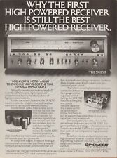
Back in the mid-seventies, if you wanted the most powerful receiver in the world, you had one choice - the Pioneer SX-1250. Introduced in 1976 at a retail price of $900 (over $3,700 in 2015 dollars!), the SX-1250 at 160 watts per channel was the second generation "monster receiver" offered by Pioneer, successor to the 110 watt per channel SX1010 first offered in 1974. In an escalating competition with Marantz, Sansui, and Kenwood for bragging rights as manufacturer of the world\'s most powerful receiver, Pioneer engineers spared no expense in designing an amazing piece of equipment that has become a legend among audiophiles worldwide - even to this day. In subsequent years, more powerful receivers have been constructed and marketed, but in my humble opinion, the SX-1250 outshines them all. Why?
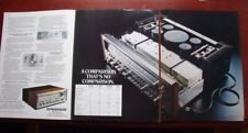
It has one of the most robust power supplies ever incorporated into any receiver. The SX-1250 employs a huge dual secondary toroidal power transformer flanked by four massive, soup-can-sized filter capacitors to supply vast reserves of raw, ripple-free current. You need these current reserves to reproduce those bone-jarring musical peaks with perfect clarity, but having those huge filter caps also eliminates all traces of power supply hum and noise so during those subtle quiet passages, all you\'ll hear is the music.
It utilizes some of the best electronic shielding used in any vintage receiver. It\'s extremely difficult to keep a powerful receiver quiet. There\'s a lot of circuitry packed into that cabinet, all doing different things, not to mention powerful magnetic fields generated by the massive power transformer. Add to that, interference generated by electrical equipment and appliances in your house, and the typical receiver will pass some static, maybe some hum, maybe some spurious radio signals into the background when you\'re trying to listen to a quiet passage on a CD. Not the Pioneer SX-1250. Both of the super-noise-sensitive tuner circuit boards are built with metal boxes shielding them on all sides. Same for the tone control circuitry, and for the preamp circuitry and even the switching boards. In fact, when you pop the cover on this masterpiece, virtually all you see is metal. Literally no expense has been spared to ensure you have the cleanest, quietest backdrop to your musical experience.
You can still get all the parts! Most folks don\'t think about this, but if you want your investment to last, you want to make sure that it\'s built with the fewest obsolete parts as possible. This isn\'t always easy when it comes to vintage 38-year-old audio equipment. Believe it or not, the Pioneer SX-1250 contains no parts that can\'t still be obtained new, or at least be replaced with new cross-referenced parts today. Well, okay, maybe the big power transformer would be tough to find, but I\'ve never ever heard of a Pioneer toroidal power transformer going \'south\', nor have I heard of anyone else who has. This unit uses no unobtainable dual-section filter caps, no obsolete RET, VFET, or flat-pack output devices, nor any "unobtanium" proprietary tuner ICs used in many subsequent monster receivers.
The bottom line is simply that the Pioneer SX-1250 represents arguably the best value in a high-power vintage receiver today, bar none. Back in \'76, The Pioneer corporation engineered and built what was then, simply the finest receiver in the world. In the humble opinion of a guy who\'s been working on and enjoying vintage audio gear since the early \'70\'s, it\'s still the best of the best.
Condition:
Cosmetically, after taking everything into consideration, this unit is truly in outstanding condition - not perfect, mind you, but all imperfections are quite minor and require close inspection to even notice. The walnut-veneered cabinet: Very nice, with some minor wear discernible, but you really have to do a close inspection to see it. There is a small nick on the top-facing surface, and a short dark streak - perhaps a light burn mark. The front walnut faceplate strips are excellent.All of the original factory stickers are still in place. The faceplate and chassis: Very, very nice - a small nick on the upper edge of the faceplate is the only issue worthy of mention - you can just barely see it in the photos. The top-facing edge of the metal faceplate on these receivers is usually pretty badly scratched up, but not on this one - it\'s almost perfect (see pics). There is no corrosion anywhere on this unit - even the interior sparkles with mint-sheen. The AM rod antenna, broken on many of these classic Pioneers, is in place and adjusts properly throughout its travel. The original factory preamp to amp jumpers are also present, as are the original padded feet.
Functionally, this receiver is without question a 10 out of 10 - and very possibly better. It\'s been thoroughly and completely restored, including a full power supply board rebuild, a complete electrolytic capacitor replacement, a conversion of indicator lamps to LEDs, and much, much more (for full details of all restoration services performed, please see below.) All controls work smoothly and are completely noise-free as are all lever and pushbutton switches. The FM section has been meticulously aligned and is unbelievably sensitive, not only pulling in my rural FM stations in stereo without any antenna connected, but pegging the signal strength meter when using only an 18" wire (that\'s what I used to take the pictures)! Finally, the amp - channels well-balanced, nice and quiet at idle, with no hum or abnormal noise in either channel, and enough power to really blow your hair back. The original factory-matched driver and output transistors are present and healthy, so that wonderful Pioneer sound remains uncompromised. This receiver simply performs magnificently all around. If you\'re looking for a top-notch \'70\'s receiver literally built to last a lifetime, you could easily spend hundreds more, but you simply won\'t find a better looking, better built, or better performing example than this beautiful Pioneer SX-1250.
Photos: (Quite a few - please allow time to load...)
Some shots of the interior. Note the presence of metal shielding everywhere. Even the foil sides of the four vertically-mounted rear circuit boards are all shielded. As a result, all hum and external interference is completely eliminated from the signal line.
Here, the tuner and phono shields have been removed. Every electrolytic capacitor you see is brand new, and of equal if not better quality than the originals.
Restoration Notes:
Here\'s a photo of the regulated power supply board before reconditioning. If the SX-1250 can be said to have any design weakness at all, it would be this board. It\'s mounted vertically in the receiver to create a "chimney" effect, so that it can be convectively cooled by rising heat currents. Nevertheless, it still gets extremely hot - particularly if the receiver is operated in a cabinet or other enclosed environment. Heat kills electronic components, and those on this board are usually the first to go. The same board, after restoration. All electrolytic capacitors have been replaced with brand new high-temperature equivalents, most rated to 105°C (221°F) - as compared to only 85°C (185°F) for the originals. All transistors have been replaced, most of them with larger, higher current-capable devices. All diodes, including zeners, were also replaced, and the old trim pots were upgraded to new Bourns precision trimmers. And that\'s just the top side of the board!
This is the foil side of the un-restored regulated power supply board, illustrating the disastrous effect of high heat on solder joints. Each yellow arrow is pointing to a potentially compromised solder joint, identified by a circular "ring crack" surrounding the wire. These little rings, caused by the differing heat expansion coefficients between the wire and the solder, eventually lead to intermittent connections - and ultimately to the failure of the receiver. Here\'s the same board, after a proper reflowing of all solder joints and a good cleaning (the yellow box outlines the area shown on the previous photo). Good, long-lasting solder joints should be well-domed and shiny. Top-quality Kester brand silver-bearing solder was used to refresh the joints on this board, and for all other solder work done on this receiver.
38 years can really build up some serious oxidation on silver-coated copper connecting pins, and Pioneer used dozens of them for the plug-in circuit boards on this receiver. Since dirty, oxidized connecting pins are at the root of many maladies plaguing old vintage receivers, a through cleaning of each and every one is in order. The photo below shows both amplifier boards; one with cleaned pins and one without. The difference is striking.
This is the protection board, prior to restoration. This is not the way this board came from the factory - apparently it had been serviced by a technician without access to the proper parts. This board contains circuitry that, among other things, protects your speakers by disconnecting the receiver from them in the event of a fault. Obviously, it\'s a good idea to ensure this speaker protection circuitry is in tip-top shape. In addition to replacing all electrolytic capacitors on this board, all transistors in the protection relay circuit were replaced with new, beefier ones designed to handle more current and more heat. Finally, a brand new CORRECT speaker protection relay has been installed.
Here\'s the fused power board, before and after "recapping". Note that the large grey "soft-start" resistor has been stressed. In addition to replacing all electrolytic capacitors on this board, a replacement resistor was obtained and installed, along with a new fusible link (the small silver device next to the resistor).
Here\'s the chassis, after being stripped down and thoroughly cleaned. This is a VERYwell-preserved receiver - not a spot of corrosion anywhere! The old filter capacitors (left) compared with the new. In addition to refreshing the tired, 38-year-old filters, the new ones can handle 25% higher working voltage AND also have the ability to withstand higher temperatures.
Here, we\'re testing the old filter capacitors. Originally rated at 22,000µF, this particular filter has lost almost a third of its ability to store a charge. The other three weren\'t much better. Just to confirm the new filter capacitors were \'up to snuff\', they were subjected to the same testing as the old ones. As expected, all of the new filters tested at or above their rated capacitance.
This is the tone amp board, prior to "recapping". The small blue oval-shaped devices are tantalum capacitors, very popular in the \'70\'s due to their relatively high capacitance, durability, and small form factor. Today however, many audiophiles maintain that tantalum capacitors, when used in the signal path, impart a harshness to the sound. Moreover, when tantalum caps do fail, they tend to short-circuit, which can lead to receiver damage. A good restoration, therefore, includes replacement of all tantalum capacitors along with the more common cylindrical electrolytic capacitors. And, the tone amp, after recapping. All capacitors in the signal path here, and on all other boards in this receiver, have been replaced with top-quality audio-grade Nichicon "UKW" series components. By the way, as the transistors on this board are known to cause noise troubles, they have been preemptively replaced with modern low-noise Fairchild equivalents. All potentiometers and switches have been thoroughly cleaned and preserved with professional-grade Caig products (Deoxit, Faderlube, etc.).
This is the \'flat amp\' board, prior to restoration. In addition to electrolytic & tantalum capacitor replacement, the all controls and switches have been thoroughly cleaned and preserved with Caig Deoxit products. The volume control requires special treatment, however... The volume control in this receiver is actually a \'stepped attenuator\' of sealed design, and therefore must be desoldered and disassembled to be properly cleaned and deoxidized.
After removal and disassembly, the volume control is thoroughly flushed with Caig Deoxit D5 cleaner, blown out with compressed air, and then lubricated with Caig Faderlube F5. As a result, the volume control now operates like new - with absolutely no noise or scratchiness. The flat amp board, completely restored, and ready for the next 38 years!
Here\'s the phono amplifier board, after restoration. The old parts are shown at left. Several tantalum caps were replaced here as well. Each and every switch in the receiver, no matter how difficult to get at, is accessed and thoroughly sluiced with Deoxit G5 Gold cleaner and preservative.
The left channel power amplifier board, in its original state. Some previous work has been done here as well - the three elecgtrolytic capacitors at front right are non-original, and of inferior quality. No matter, since we\'ll be replacing all of the electrolytics anyway. Here\'s an excellent example of why a good restoration includes removing, cleaning and remountingHere\'s an excellent example of why a good restoration includes removing, cleaning and remounting all heat-sinked transistors. The white crumbly material below started its life as thermal transfer compound, a grease-like material designed to help its transistor "off-load" the considerable heat it generated to the larger metal heat sink. Over time though, this heat transfer compound breaks down, and can actually become an impediment to good heat transfer.
The transistor and heat sink are cleaned, and fresh thermal transfer compound is applied to a new mica insulator and to the cleaned transistor. Technique is important here as well - too much or too little thermal compound can actually be an impediment to optimal heat transfer. A thin, slightly translucent coating is what we\'re after. Both power amp boards receive all-new caps, and new Bourns trimmer resistors (the blue boxes). The DC offset trimmer has been upgraded to a 12-turn type, which makes it much, much easier to zero out DC on the speakers, which is done later. The large heat-sinked driver transistors have been removed, cleaned, and remounted with new mica insulators and fresh thermal compound. Finally, the connecting pins are all burnished and all solder joints on the back side are carefully inspected and reflowed as needed.
Time to put the amps back together. The big power transistors all receive a fresh coat of thermal transfer compound, and are remounted using brand new mica insulators. All heat-sink mounted transistors in the receiver get the same treatment. This keeps these high-current devices running as cool and efficiently as possible. The right channel outputs, remounted. Before reinstallation, the pins of all eight output transistors are thoroughly cleaned to ensure the best possible contact. This receiver has all of its original factory-matched driver and output transistors in place, so that magical Pioneer sound quality remains uncompromised.
The amplifier connectors all receive a spritz of Deoxit, pin by pin, to assure the best connection and minimize future contact point oxidation. Fresh thermal compound is applied to the bias diodes prior to their reattachment to their heat sinks. As these diodes are critical in ensuring proper idle current flow through the output devices as they heat up, good thermal contact here is a must.
And here we have the tuner/MPX board, before and after. Most folks who do vintage restoration work shy away from replacing tuner circuitry capacitors, citing fears that it would negatively affect the receiver\'s tuner alignment. In my experience though, I find that the exact opposite is true. Initially, this SX-1250 wasn\'t quite as sensitive as some I\'d seen, however after a tuner board recap and a careful alignment, the FM reception improved dramatically, and now ranks with the best of them. I have full stereo reception of most available stations here in my rural locale - without even an antenna connected! FM DX\'ers, you will NOT be disappointed with this one!