When you click on links to various merchants on this site and make a purchase, this can result in this site earning a commission. Affiliate programs and affiliations include, but are not limited to, the eBay Partner Network.
Pioneer SX-1250 Stereophonic Receiver
Description:
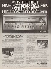
Back in the mid-seventies, if you wanted the mostpowerful receiver in the world, you had one choice - the Pioneer SX-1250. Introduced in 1976 at a retail price of $900 (over $3,700 in 2015 dollars!), the SX-1250 at 160 watts per channel was the second generation "monster receiver" offered by Pioneer, successor to the 110 watt per channel SX1010 first offered in 1974. In an escalating competition with Marantz, Sansui, and Kenwood for bragging rights as manufacturer of the world\'s most powerful receiver, Pioneer engineers spared no expense in designing an amazing piece of equipment that has become a legend among audiophiles worldwide - even to this day. In subsequent years, more powerful receivers have been constructed and marketed, but in my humble opinion, the SX-1250 outshines them all. Why?
It has one of the most robust power supplies ever incorporated into any receiver. The SX-1250 employs a huge dual secondary toroidal power transformer flanked by four massive, soup-can-sized filter capacitors to supply vast reserves of raw, ripple-free current. You need these current reserves to reproduce those bone-jarring musical peaks with perfect clarity, but having those huge filter caps also eliminates all traces of power supply hum and noise so during those subtle quiet passages, all you\'ll hear is the music.
It utilizes some of the best electronic shielding used in any vintage receiver. It\'s extremely difficult to keep a powerful receiver quiet. There\'s a lot of circuitry packed into that cabinet, all doing different things, not to mention powerful magnetic fields generated by the massive power transformer. Add to that, interference generated by electrical equipment and appliances in your house, and the typical receiver will pass some static, maybe some hum, maybe some spurious radio signals into the background when you\'re trying to listen to a quiet passage on a CD. Not the Pioneer SX-1250. Both of the super-noise-sensitive tuner circuit boards are built with metal boxes shielding them on all sides. Same for the tone control circuitry,and for the preamp circuitry and even the switching boards. In fact, when you pop the cover on this masterpiece, virtually all you see is metal. Literally no expense has been spared to ensure you have the cleanest, quietest backdrop to your musical experience.
You can still get all the parts! Most folks don\'t think about this, but if you want your investment to last, you want to make sure that it\'s built with the fewest obsolete parts as possible. This isn\'t always easy when it comes to vintage 38-year-old audio equipment. Believe it or not, the Pioneer SX-1250 contains no parts that can\'t still be obtained new, or at least be replaced with new cross-referenced parts today. Well, okay, maybe the big power transformer would be tough to find, but I\'ve never ever heard of a Pioneer toroidal power transformer going \'south\', nor have I heard of anyone else who has. This unit uses no unobtainable dual-section filter caps, no obsolete RET, VFET, or flat-pack output devices, nor any "unobtanium" proprietary tuner ICs used in many subsequent monster receivers.
The bottom line is simply that the Pioneer SX-1250 represents arguably the best value in a high-power vintage receiver today, bar none. Back in \'76, The Pioneer corporation engineered and built what was then, simply the finest receiver in the world. In the humble opinion of a guy who\'s been working on and enjoying vintage audio gear since the early \'70\'s, it\'s still the best of the best.
Condition:
Pioneer SX-1250\'s just don\'t get much better than this one. The faceplate is essentially perfect, with no marks, scratches, or other obvious signs of wear. The knobs and switch covers - perfect. The top-facing edge of the metal faceplate on these receivers is usually pretty badly scratched up, but not on this one - it\'s also virtually perfect (see pics). The original veneered case for this receiver had a pretty deep gouge in it, so I replaced it with a brand new, custom-made, solid walnut case, including brand new solid walnut faceplate edge-blocks. The only flaw in this receiver worth mentioning is a small chip in the left rear heat sink that occurred during shipping to me. I was able to glue the chip back in place, but if you look carefully, you can see the repair. I\'ve included a close-up shot of this below. There is no corrosion anywhere on this unit - even the interior sparkles with mint-sheen. The AM rod antenna, broken on many of these classic Pioneers, is in place and adjusts properly throughout its travel. The original factory preamp to amp jumpers are also present, as are the original padded feet. This may very possibly be the nicest SX-1250 you\'re ever likely to find. Don\'t let it get away!
Functionally, this receiver is without question a 10 out of 10 - and very possibly better. It\'s been thoroughly and completely restored, including a full power supply board rebuild, a complete electrolytic capacitor replacement, a conversion of indicator lamps to LEDs, and much, much more (for full details of all restoration services performed, please see below.) All controls work smoothly and are completely noise-free as are all lever and pushbutton switches. The FM section has been meticulously aligned and is unbelievably sensitive, not only pulling in my rural FM stations in stereo without any antenna connected, but pegging the signal strength meter when using only an 18" wire (that\'s what I used to take the pictures)! Finally, the amp - channels well-balanced, nice and quiet at idle, with no hum or abnormal noise in either channel, and enough power to really blow your hair back. The original factory-matched driver and output transistors are present and healthy, so that wonderful Pioneer sound remains uncompromised. This receiver simply performs magnificently all around. If you\'re looking for a top-notch \'70\'s receiver literally built to last a lifetime, you could easily spend hundreds more, but you simply won\'t find a better looking, better built, or better performing example than this beautiful Pioneer SX-1250.
Photos:
PLEASE NOTE: Only after processing and uploading all of the photos below, did I notice that the tuning meters weren\'t quite aligned within their windows. This took all of five minutes to remedy, and the meters are now centered perfectly. I hope prospective buyers will forgive me for not lugging this beast back to my kitchen island and re-taking all of the pictures!
Some shots of the interior. Note the presence of metal shielding everywhere. Even the foil sides of the four vertically-mounted rear circuit boards are all shielded. As a result, all hum and external interference is completely eliminated from the signal line.
Here, the tuner and phono shields have been removed. All electrolytic capacitors you see are brand new, and of equal if not better quality than the originals.
Restoration Notes:
Here\'s a photo of the regulated power supply board before reconditioning. If the SX-1250 can be said to have any design weakness at all, it would be this board. It\'s mounted vertically in the receiver to create a "chimney" effect, so that it can be convectively cooled by rising heat currents. Nevertheless, it still gets extremely hot - particularly if the receiver is operated in a cabinet or other enclosed environment. Heat kills electronic components, and those on this board are usually the first to go. The same board, after restoration. All electrolytic capacitors have been replaced with brand new high-temperature equivalents, most rated to 105°C (221°F) - as compared to only 85°C (185°F) for the originals. All transistors have been replaced, most of them with larger, higher current-capable devices. All diodes, including zeners, were also replaced, and the old trim pots were upgraded to new Bourns precision trimmers. And that\'s just the top side of the board!
This is the foil side of the un-restored regulated power supply board, illustrating the disastrous effect of high heat on solder joints. Each yellow arrow is pointing to a potentially compromised solder joint, identified by a circular "ring crack" surrounding the wire. These little rings, caused by the differing heat expansion coefficients between the wire and the solder, eventually lead to intermittent connections - and ultimately to the failure of the receiver. Here\'s the same board, after a proper reflowing of all solder joints and a good cleaning (the yellow box outlines the area shown on the previous photo). Good, long-lasting solder joints should be well-domed and shiny. Top-quality Kester brand silver-bearing solder was used to refresh the joints on this board, and for all other solder work done on this receiver.
38 years can really build up some serious oxidation on silver-coated copper connecting pins, and Pioneer used dozens of them for the plug-in circuit boards on this receiver. Since dirty, oxidized connecting pins are at the root of many maladies plaguing old vintage receivers, a through cleaning of each and every one is in order. The regulated power supply is the most important board to get right when restoring a Pioneer SX-1250. Everything has been replaced with new, except for the resistors, which were all leg-lifted and tested for values within manufacturer\'s tolerance. The old parts are shown below.
This is the protection board, prior to restoration. This board contains circuitry that, among other things, protects your speakers by disconnecting the receiver from them in the event of a fault. Obviously, it\'s a good idea to ensure this speaker protection circuitry is in tip-top shape. In addition to replacing all electrolytic capacitors on this board, all transistors in the protection relay circuit were replaced with new, beefier ones designed to handle more current and more heat. You can see these three new larger transistors in the lower left corner of the board.
Here\'s the fused power board, before and after "recapping". Modern advances in manufacturing technology allow for capacitors to be manufactured in much smaller packages than in the \'70\'s, as can be evidenced by the significantly smaller equivalent replacement capacitors installed below.
Here\'s the chassis, after being stripped down and thoroughly cleaned. This is a VERYwell-preserved receiver - not a spot of corrosion anywhere! The old filter capacitors (left) compared with the new. In addition to refreshing the tired, 38-year-old filters, the new ones can handle 25% higher working voltage AND also have the ability to withstand higher temperatures.
Here, we\'re testing the old filter capacitors. Originally rated at 22,000µF, this particular filter has lost almost a quarter of its ability to store a charge. The other three weren\'t much better. Just to confirm the new filter capacitors were \'up to snuff\', they were subjected to the same testing as the old ones. As expected, all of the new filters tested at or above their rated capacitance.
This is the tone amp board, prior to "recapping". The small blue oval-shaped devices are tantalum capacitors, very popular in the \'70\'s due to their relatively high capacitance, durability, and small form factor. Today however, many audiophiles maintain that tantalum capacitors, when used in the signal path, impart a harshness to the sound. Moreover, when tantalum caps do fail, they tend to short-circuit, which can lead to receiver damage. A good restoration, therefore, includes replacement of all tantalum capacitors along with the more common cylindrical electrolytic capacitors. And, the tone amp, after recapping. All capacitors in the signal path here, and on all other boards in this receiver, have been replaced with top-quality audio-grade Nichicon "UKW" series components. By the way, as the transistors on this board are known to cause noise troubles, they have been preemptively replaced with modern low-noise Fairchild equivalents. All potentiometers and switches have been thoroughly cleaned and preserved with professional-grade Caig products (Deoxit, Faderlube, etc.).
This is the \'flat amp\' board, prior to restoration. In addition to electrolytic & tantalum capacitor replacement, all of the controls and switches have been thoroughly cleaned and preserved with Caig Deoxit products. The volume control requires special treatment, however... The volume control in this receiver is actually a \'stepped attenuator\' of sealed design, and therefore must be desoldered and disassembled to be properly cleaned and deoxidized.
After removal and disassembly, the volume control is thoroughly flushed with Caig Deoxit D5 cleaner, blown out with compressed air, and then lubricated with Caig Faderlube F5. As a result, the volume control now operates like new - with absolutely no noise or scratchiness. The flat amp board, completely restored, and ready for the next 38 years!
Here\'s the phono amplifier board, before and after restoration. Several tantalum caps were replaced here as well.
The left channel power amplifier board, in its pristine original state. One of the nice attributes of this particular SX-1250 is the fact that nobody had ever opened it and worked on it before I acquired it. Many technicians out there, while undoubtedly knowledgeable and talented, nevertheless are paid by how efficiently and quickly they can repair equipment. This doesn\'t lend itself well to the careful, high-quality restoration work a classic like the SX-1250 deserves. Both power amp boards receive all-new caps, and new Bourns trimmer resistors (the blue boxes). The DC offset trimmer has been upgraded to a 12-turn type, which makes it much, much easier to zero out DC on the speakers, which is done later. The large heat-sinked driver transistors have been removed, cleaned, and remounted with new mica insulators and fresh thermal compound. Finally, the connecting pins are all burnished and all solder joints on the back side are carefully inspected and reflowed as needed.
Now that the boards have been refreshed, it\'s time to put the amps back together. The big power transistors all receive a fresh coat of thermal transfer compound, and are remounted using brand new mica insulators. All heat-sink mounted transistors in the receiver get the same treatment. This keeps these high-current devices running as cool and efficiently as possible. Here are the right channel output transistors, remounted. Before reinstallation, the pins of all eight output transistors are thoroughly cleaned to ensure the best possible contact. This receiver has all of its original factory-matched driver and output transistors in place, so that magical Pioneer sound quality remains uncompromised.
The amplifier connectors all receive a spritz of Deoxit, pin by pin, to assure the best connection and minimize future contact point oxidation. All plug-in connectors throughout the receiver have been deoxidized/preserved in the same manner. While we have the Deoxit out, now\'s a good time to clean all of the connectors and jacks. A pipecleaner soaked in Deoxit Gold G5 cleans the connectors\' inner surfaces and leaves a preservative which retards future oxididation.
And here we have the tuner/MPX board, before and after. Most folks who do vintage restoration work shy away from replacing tuner circuitry capacitors, citing fears that it would negatively affect the receiver\'s tuner alignment. In my experience though, I find that the exact opposite is true. Initially, this SX-1250 wasn\'t quite as sensitive as some I\'d seen, however after a tuner board recap and a careful alignment, the FM reception improved dramatically, and now ranks as possibly the most sensitive SX-1250 I\'ve ever seen. I have full stereo reception of most available stations here in my rural locale - without even an antenna connected! FM DX\'ers, you will NOT be disappointed with this one!/strong> than the thinly-veneered original and really puts the perfect finishing touch on this beautiful, completely restored receiver.
AAll knobs and buttons are carefully cleaned with a toothbrush to remove every bit of dirt from every crevice, and then polished to a mirror-like finish. The faceplate is likewise cleaned and polished, the glass burnished with a microfiber cloth. Other than the day it was boxed, this SX-1250 has never been cleaner!/strong>
Setting up for final adjustment and testing. To either side of the receiver are four large 8-Ohm load resistors - we\'ll need these for accurately testing power output. Dialing in the regulated supply voltage to an exact ±65 VDC, as specified in the service manual. Getting this voltage correct is important, as it feeds most of the circuitry in the receiver.
Zeroing out any DC voltage on the speaker terminals. DC on your outputs is bad, as it can cause distortion in small amounts, and damage your speakers in large amounts. Getting within a few millivolts of zero is great. This receiver can be zeroed under one millivolt on each channel. Bottom line, this is a very healthy, stable receiver. After warming up, the idle current can be dialed in within a few tenths of a millivolt to the factory spec of 100 mV. (Generally, a 10% variation is acceptable, so you can get an idea of just how stable the output circuitry on this receiver really is!) "Idle current" (a.k.a. "bias current") is a small amount of electric current supplied to the output transistors to ensure that they never completely shut off. Getting it properly adjusted is important - if it\'s set too low, sound quality can become harsh due to \'switching distortion\'. If it\'s set too high, the the output transistors run too hot and can become damaged.
Okay, now that we\'ve put so much time and effort into getting this ol\' girl back in tip-top shape, let\'s find out what she\'s really got under the hood. We\'re testing the SX-1250\'s power output just before clipping, with both channels driven into 8-Ohm load resistors. Notice the nice clean 1 KHz traces on the scope for both channels, just slightly offset from each other so you can confirm matching amplitude. You can see 39.42 VAC on the right true RMS voltmeter - right channel power output = E2/R = 1553.9 ÷ 8 = 194.2 Watts. Left channel measured 193.3 Watts. Well-balanced and definitely some power to spare, but wait..... And now... the "acid" test. Running 4-Ohm bench tests is scary because there aren\'t too many amplifiers designed to safely handle such a low load impedance (you subject a receiver to a 4-Ohm load whenever you hook up two sets of 8-Ohm speakers and run all four at once). Unlike some of their later models, Pioneer actually provides specifications for the SX-1250 into a 4-Ohm load, so they obviously felt confident that this receiver could handle it. For each channel, two 8-Ohm load resistors are connected in parallel to yield 4-Ohm loads, and the same 1kHz tone is amplified until just before the waveform on the oscilloscope begins to distort. Checking the right channel, P = E2/R = (33.18 x 33.18) ÷ 4 = 275.2 Watts. Right channel comes in at 272.1 Watts. Pioneer says the SX-1250 can put 200 watts into a 4-Ohm load. I\'d say they were being extremely modest. Wow!
A shot of the included literature. The owner\'s manual and fold-out schematic diagram are factory originals, the rest are high-quality color copies using a professional solid-ink printer.
Finally, a shot of all of the original parts that have been replaced in this restoration. The winning buyer is welcome to these at his/her option - please let me know after the sale.
Restoration Services Provided:
- All electrolytic and tantalum capacitors on all boards (including tuner board) replaced with brand new components:
- All electrolytic caps in signal path replaced with Nichicon Audio Grade "UKW" series
- All electrolytic caps in power supply and smoothing applications replaced with Nichicon 105°C Hi-Temp "UPW" series
- Original 22,000 µf 80V 85°C filter caps replaced with brand new Nippon Chemicon 22,000 µf 100V 95°C
- All small electrolytic caps (less than 2 µf) replaced with new Panasonic polypropylene capacitors
- All transistors and diodes replaced on critical regulated power supply circuit board
- Bias, offset, and regulated supply trimmer resistors replaced with new Bourns equivalents
- Trouble-prone 2SA725, 2SC1313, and 2SC1312 preamp transistors replaced with modern low-noise equivalents
- Speaker protection relay replaced with new Omron equivalent
- Protection circuit driver transistors replaced with more robust devices
- Incandescent dial lamps replaced with brand-new 8V 300 mA long-life bulbs
- All incandescent function indicator lamps replaced with long-life (100,000 hour) LED devices
- Regulated power supply adjusted to exact factory spec (65VDC)
- DC offsets zeroed and idle currents set to spec (100mA), after 30 minute warm up/stabilization period
- All rotary potentiometers cleaned with Caig Deoxit D5 and lubricated with Caig Faderlube F5
- Sealed volume attenuator desoldered, disassembled, cleaned and lubed as above, reinstalled
- All rotary and pushbutton switches cleaned with Caig Deoxit D5 and preserved with Caig DeOxit G5 Gold
- All heat-sink-mounted driver and output transistors removed, cleaned, and remounted with fresh thermal transfer compound and new mica insulators
- Tuning capacitor bearings cleaned and lubricated, main tuning knob bearing and all dial string pulleys lubricated
- All RCA-style inputs, dubbing jacks and headphone jack internally and externally cleaned and deoxidized
- Full FM front-end and discriminator alignment performed
- Dial pointer precisely calibrated via local oscillator touch-up
- Chassis and all circuit boards cleaned; all plug-in connecting pins burnished
- Silver-bearing solder used in all replacements, and to reflow any other suspect joints
- ONE YEAR full parts and labor warranty included *
What You Get:
- Pioneer SX-1250 receiver, serial #XL3630676S, manufactured in December, 1977
- Original SX-1250 Handbook of Instructions
- Original SX-1250 fold-out schematic diagram
- Full color high resolution duplexed copy of full service manual for the SX-1250
- Color duplexed copy of five-page detailed promotional brochure for the SX-1250
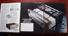
- Copies of magazine print ads for the SX-1250
- Full listing of all parts used in this restoration, including supplier part numbers and restoration notes
- All old removed parts (optional - please let me know if you want these)
Features:
- 160 watts per channel at 8 ohms, 200 watts per channel into 4 ohms!
- Power In and Pre Out jacks allow unit to be used with separate preamp or power amp
- 30Hz & 8kHz tone filters for ultra clean low and high ranges
- Dual bass controls (50Hz and 100Hz) for precision low frequency control
- Dual treble controls (10kHz and 20kHz) for precision high frequency control
- Tone defeat switch for the purest, most accurate reproduction of any source material
- Three separate speaker outputs, any two of which may be used together
- Numerous Inputs - Phono 1, Phono 2/Mic, AUX, Tape 1, and Tape 2, and \'Adaptor loop\' (can be used as Tape 3!)
- Signal Strength & Tuning Meters for ultimate reception of AM & FM bands
- -20 dB audio muting switch - perfect when the phone rings!
- 25µS / 50µS / 75µS rear panel FM De-emphasis switch
- FM Multipath button
- FM Muting button
- Three rear accessory outlets
- And more...
Specifications:
Power Output: 160 watts per channel RMS into 8 ohms, 200 watts per channel into 4 ohms, 20 Hz to 20 KHz Harmonic Distortion: Less than 0.1% at full rated power into 8 or 4 ohms, no more than 0.05% at 80 watts/channel Intermodulation Distortion: Less than 0.1% at full rated power into 8 or 4 ohms, no more than 0.05% at 80 watts/channel Frequency Response: 5 Hz to 100 kHz, + 0 dB, - 1 dB Hum & Noise: 100dB FM Sensitivity: 1.5µV FM Capture Ratio: 1.0 dB FM Harmonic Distortion Mono: Less than 0.10% @ 1kHz FM Harmonic Distortion Stereo: Less than 0.25% @ 1kHz Damping Factor at load impedance: 30, 20 Hz to 20 kHz into 8 ohms Dimensions (W" x H" x D"): 21-7/8 x 7-3/8 x 18 -1/4 Weight (Unpacked): 64.3 lbs.
Terms:
If you are not 100% satisfied with this unit, you may return it within 14 days of receipt for a full refund of your purchase price and original outbound shipping (yes, return shipping would be your responsibility). Full refund would of course be contingent upon receiving the returned unit in the same condition in which it was sent, without any missing or exchanged parts.
*As most failure-prone parts in this receiver have already been replaced, I am happy to offer a full one year warranty on this unit. Should you have any problems within one year of receiving this item, I will repair it free of charge, including parts and labor, provided you handle round-trip shipping.
Due to guidelines, I accept only PayPal payment. Buyer pays fixed FedEx Ground shipping rate of $85.00, which includes shipping insurance and absolutely bulletproof packaging, for any destination in the continental US. Buyer MUST respond within 3 days of the sale end or transaction will be void. Payment MUST be received within 10 days of the end of the sale or the transaction will be void. I reserve the right to cancel offers from any party with a response rating at or below zero, or any party with excessive negative response. Good luck and happy offerding!